


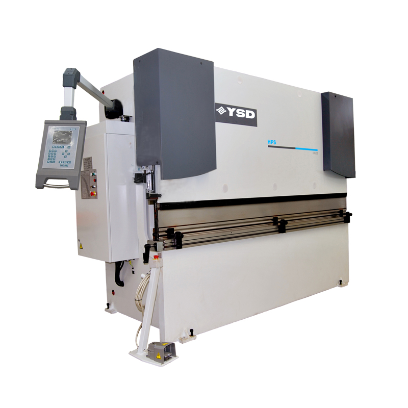
As professional metal forming machine manufacturer and supplier, we provide HPS series press brakes. These bending machines can offer optimal accuracy with electric-hydraulic servo system and advanced CNC machine. The bending process can be set according to customers’ requirements. The non-corrosive surface allows much less maintenance for the press brakes. Special materials will be packed together to avoid possible damage during delivery. Our company offer excellent after-sale service and could help you know all the affecting factors to obtain the optimal bending process and accurate bending results.
Characteristics
- HPS Series Press Brakes are equipped with electric-hydraulic servo system and allow for synchronous movement controlled by fully closed loop.
- These bending machines feature in a back gauge driven by servo motor and a ball screw guided by two linear bearings.
- Advanced CNC machine allows for data rectifying process, so as to ensure accuracy.
- Ram deflection can be compensated with crowning on working table.
- A variety of combination of top tooling and bottom tooling is available for customers.
- Linear encoders
Linear encoders for ram position measuring contribute to optimal accuracy.
- Control technology
Two linear encoders (Y1-Y2) are set on two sides of the press brakes, which are used to measure the exact distance between the ram and worktable. The encoders are connected to the table so as to prevent deformation of the side frames from affecting positioning. In addition, the obtained data is immediately sent to the control system for calculation and then the servo valves receive the corresponding control signal. CNC system is used to rectify two servo calves in case of any error. Also, it always ensures the parallel state between the ram and worktable of the bending machine.
- Machine Configuration
CNC crowning is set on worktable of the press brakes with double wedges moving relatively to ensure accurate bending compensation. After parameters such as sheet thickness, sheet length, die opening and tensile strength data are conveyed to control system, force and related crowning compensation value are automatically determined. It’s better to add preloading process to each bending process.
- Worktable crowning system can be controlled by hand wheel or by motor. Programmable crowning system V-axis is optional.
- Automatic back gauge system is characterized by high precision. The components include X axis transmission by gear belt driven by servo motor, servo driven R axis for vertical movement, and stopping finger with manual transverse movement.
- Equipment for option (quick clamping top tooling & special tooling & throat & back safety guarding).
(4) CNC controller DA52.
Key components:
Name Supplier Origin
Seal MERKEL or NOK Germany or Japan
Hydraulic valve unit BOSCH Germany
Linear encoder HEIDENHAIN Germany
Servo motor and servo dirve ESTUN China
Oil pump NACHI Japan
CNC system DELEM or CYBELEC Holland or Switzerland
| Model | 50/20 | 100/30 | 135/30 | 165/30 | 200/30 | 250/32 | 320/40 | 500/40 | |
| Press force | ton | 50 | 100 | 135 | 165 | 200 | 250 | 320 | 500 |
| Working Length | mm | 2050 | 3050 | 3050 | 3050 | 3050 | 3250 | 4000 | 4000 |
| Dist.between uprights | mm | 1640 | 2550 | 2550 | 2250 | 2550 | 2250 | 3150 | 3150 |
| Stroke | mm | 200 | 200 | 200 | 200 | 250 | 280 | 280 | 300 |
| Distance table/ram | mm | 380 | 400 | 400 | 400 | 450 | 520 | 520 | 600 |
| Gap | mm | 300 | 400 | 400 | 400 | 400 | 400 | 400 | 400 |
| Width of table | mm | 140 | 180 | 180 | 180 | 180 | 250 | 250 | 300 |
| Approaching speed | mm/s | 150 | 150 | 130 | 130 | 110 | 100 | 100 | 90 |
| Working speed | mm/s | 10 | 10 | 10 | 10 | 10 | 9 | 10 | 8 |
| Returning speed | mm/s | 110 | 110 | 110 | 110 | 110 | 110 | 100 | 75 |
| Motor | kW | 5.5 | 11 | 15 | 18.5 | 18.5 | 22 | 30 | 37 |
| Volume of oil tank | L | 180 | 320 | 320 | 350 | 400 | 700 | 700 | 900 |
| Traven in X axis | mm | 600 | 600 | 600 | 600 | 600 | 600 | 600 | 600 |
| Lenght of machine | mm | 2185 | 3320 | 3320 | 3320 | 3320 | 3500 | 4450 | 4600 |
| Width of machine | mm | 1450 | 1660 | 1700 | 1750 | 1900 | 2000 | 2200 | 2500 |
| Height of machine | mm | 2275 | 2500 | 2500 | 2500 | 3200 | 3700 | 3800 | 4250 |
| Weight | kg | 5000 | 7000 | 10000 | 12000 | 12500 | 15000 | 19500 | 36500 |